March: PUSHING LIMITS: Innovative Solutions for High Bandwidth, Long Distance Subsea Data Transmission
PUSHING LIMITS:
Innovative Solutions for High Bandwidth, Long Distance Subsea Data Transmission
By: Michael Greene, New Product Development Engineer, and Gregory Eskridge, New Product Development Engineer Teledyne Oil and Gas
As the sensors used in the subsea environment increase in number and capability, the amount of data transmitted by these sensors continue to increase. Some of the approaches to provide data transfer bandwidth include electrical modems, electrical DSL, electrical CAN bus, electrical Ethernet, and optical Ethernet. Conventional electrical modems can transmit data over long distances. This technology is by far the most mature for subsea use. However, the maximum data transfer rates achievable are insufficient for technologies that demand data transfer rates in excess of 20 kbps.
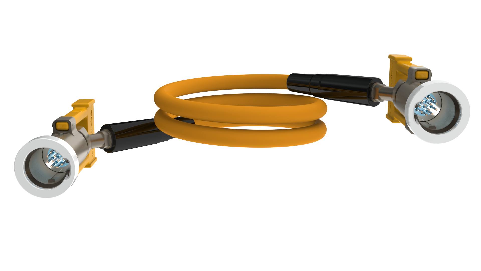 |
| A 12-way Nautilus™ Ethernet flying lead transmits Ethernet signals over custom cabling sealed to seawater ingress by two independent barriers. |
Electrical DSL offers higher bandwidth than modem technology at reasonably long distances, but the available bandwidth decreases as a function of length and still does not provide enough bandwidth for many data rich technologies (200 to 3000 kb/sec, up to 15 km). Electrical Ethernet has proven to be reliable and high bandwidth, but is limited to short step out distances (<100 m). Electrical Ethernet is extensively used for short distance subsea communications in the Oil & Gas market. Additionally, CAN bus is used subsea for many safety systems. However, system capacitance limits the distance between the CAN bus controller and its sensors. In cases where step out distances are too long or bandwidth requirements are too great, optical Ethernet is utilized. Optical Ethernet easily accommodates higher bandwidth data and is not limited to short lengths, but comes with a higher cost of implementation. This cost is not limited to the optical wetmate connectors, but also includes the optical infrastructure required in the electronics module to which the optical connectors are mated. In order to meet the future demands, two new technology fronts have been conceived. On the first front, advancements in optical wet-mate connector design now enable higher bandwidth transmission and sensing. On the second front, Active Flying Leads build on the solid reliability of Electrical Flying Leads (EFL) to add functionality to a standard piece of subsea hardware.
Optical Flying Leads (OFLs) have been used successfully in the field for about two decades. Optical wet-mate connectors come in several varieties: all-optical, such as Teledyne’s RS (Rolling Seal) connector, or as a “hybrid” with a combination of fiber connections and electrical connections with capacity of connections up to 30 amps, such as Teledyne’s NRH (Nautilus Rolling Seal) Connector.
Standard optical and hybrid connectors use an Ultra Physical Contact (UPC) polish for the optical end face, resulting in a connector-level return loss of >30 dB. However, in order to reduce Fresnel reflections at the optical interface, Angled Physical Contact (APC) polished end faces have been introduced in both RS and NRH connectors. The APC end face geometry has a polish angle of 8° compared to the 0°angle used by the UPC end face. The change in the contact angle between the two optical end faces results in a return loss typically >45 dB. Widely deployed in the terrestrial optic fiber industry, APC connectors are used when very little reflection is desired. Applications for these improved back reflection connectors include high speed communication systems with low noise requirements, all-optical sensing systems for Life of Field Seismic monitoring, or systems using higher than standard optical power. As larger data transfers and longer distances are required, this technology enables greater possibilities.
 |
|
For optical wet-mate connectors, return loss at the optical interface is improved from >30 dB to |
The newest entry into long step out data transfer is the introduction of Active Flying Leads (AFLs). AFLs are made active through the addition of electronic components. The a standard Ethernet flying lead, referred to as the Extended Ethernet Flying Lead (E²FL). Custom Ethernet cables were developed for use in Pressure Balanced Oil-filled (PBOF) jumpers, which allowed for Ethernet transmission to reach up to 100 m as allowed by ISO standards. The new cable was then combined with custom ruggedized Ethernet repeater boards that are placed inside an atmospheric chamber. The chambers were designed to be no larger in diameter than the hose bend restrictors currently used for a stream-lined integration to the flying lead. By placing a slim canister every 100 m on an Ethernet jumper, it is now possible to transmit Ethernet data up to 300 m subsea or beyond without an SEM or SCU in between. The Ethernet repeaters require 5 to 48 V to operate and are also capable of handling and retransmitting power over Ethernet, if required.
The next ongoing phase of development for the Ethernet AFLs is the introduction of a ruggedized and high reliability media converter. This media converter will convert electrical Ethernet signal in the back of a flying lead to optical and transmit for up to 10 km, then convert back to electrical on the other end with a second media converter. Two versions are being qualified to handle multiple optical wavelengths, and this technology has several possible applications. One of the most promising is the ability to connect electrical Ethernet systems to fiber optic systems in brownfield applications where connection points may be limited. Using either the E²FL or the Media Converter, length restriction for subsea projects is minimized or eliminated. In addition, optical media conversion does not have to be added to the existing electrical modules as it is incorporated into the flying lead.
 |
|
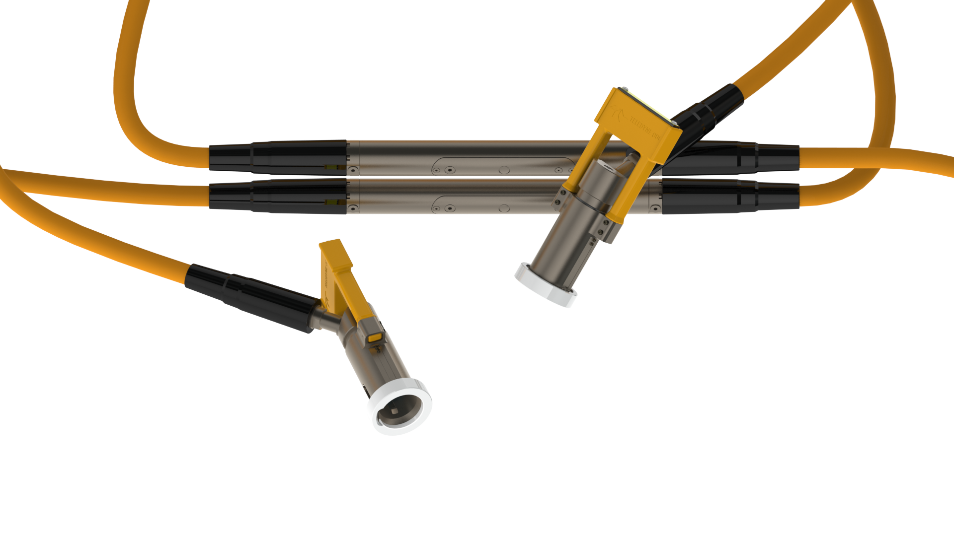
The Extended Ethernet Flying Lead (E²FL) incorporates a repeater board into the PBOF hose to |
Continuing this trend to add additional functionality into flying leads, the latest AFL development incorporates a CAN bus repeater system. The first CAN bus system to be available will allow full transparency and does not require any special communication by the user. With the addition of these circuit boards, CAN bus flying leads can reach distances of 1,500 m or longer. This technology can assist in asset monitoring of long lengths of pipe that may be isolated from monitoring equipment.
Modern and emerging sensors and systems now demand greater data transmission capability in networking options. This trend will continue to grow as sensors and systems develop further. Subsea networks will, in turn, require modular connectivity using interconnect systems capable of supporting this high bandwidth availability. Just as sensors have become more reliable over time, interconnect systems have also evolved. The need for enhanced reliability and the ability to collect complete data and confidently measure reliability is ever increasing. The introduction of AFLs and the evolution of subsea fiber optic connectors provide a platform to solve future challenges in subsea data communication.