August - Technology of the DEEPSEA CHALLENGE Expedition (Part 3 of 3: DEEPSEA CHALLENGER)
Ocean News
By: Kevin Hardy, Global Ocean Design LLC; Bruce Sutphen, Sutphen Marine LLC; and James Cameron, Earthship Productions LLC
INTRODUCTION
This required a gut check of epic proportions. “When you gaze long into an abyss, the abyss also gazes into you,” understood German philosopher Friedrich Nietzsche in 1886. With that, Explorer and Filmmaker James Cameron radioed the command to release the surface flotation and began his journey downward solo inside DEEPSEA CHALLENGER (DSC) to take on the towering odds against surviving the most extreme hyperbaric environment on Planet Earth: the western Pacific Ocean’s Mariana Trench (Figure 2).
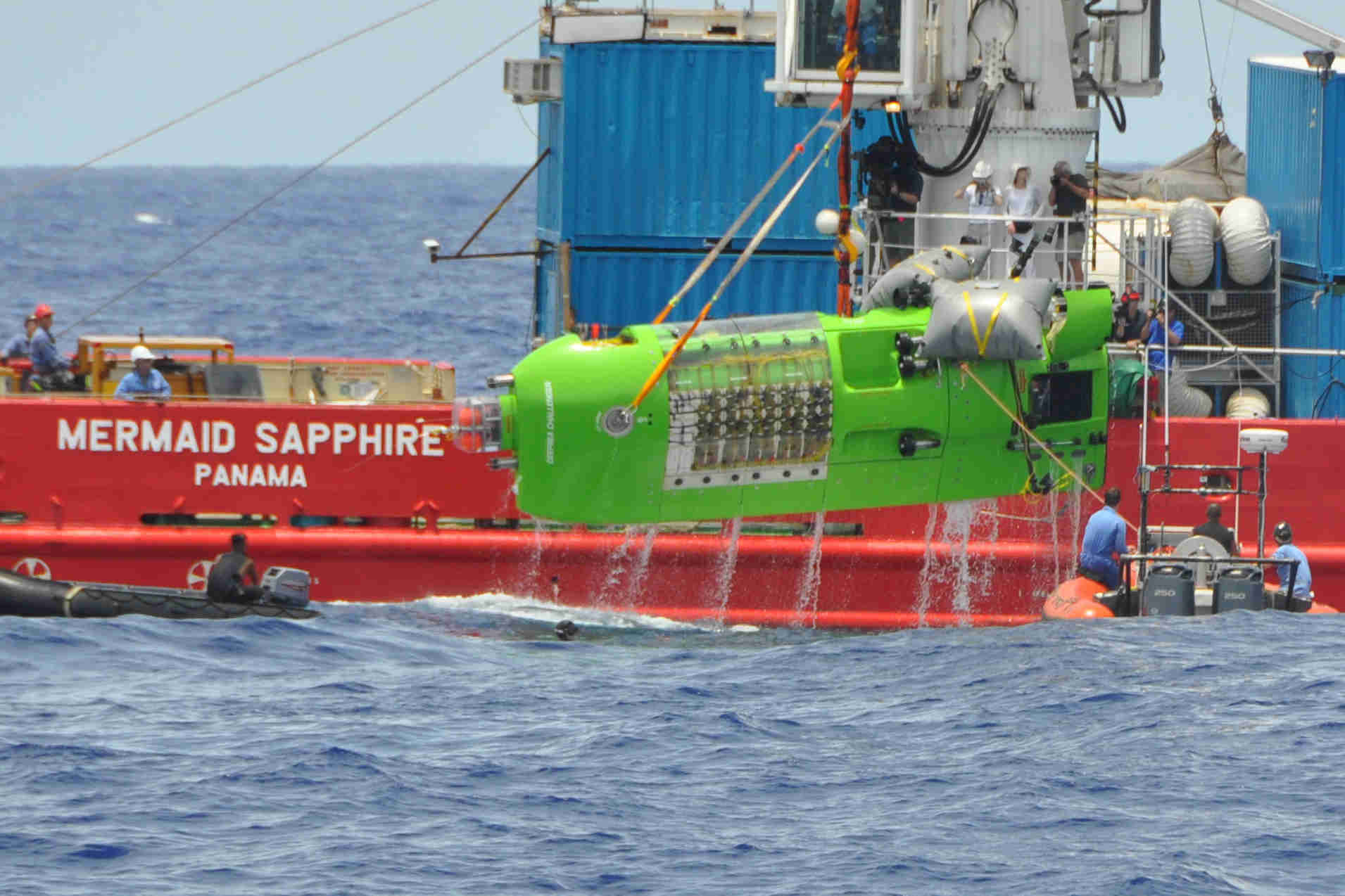 |
| Figure 2. The submersible DEEPSEA CHALLENGER, with Explorer James Cameron inside, is lifted aboard the M/V Mermaid Sapphire following its deep dive into the East Pond of the Challenger Deep in the Mariana Trench. Photo by Chris Symons. Used with permission, Earthship LLC. |
 |
|
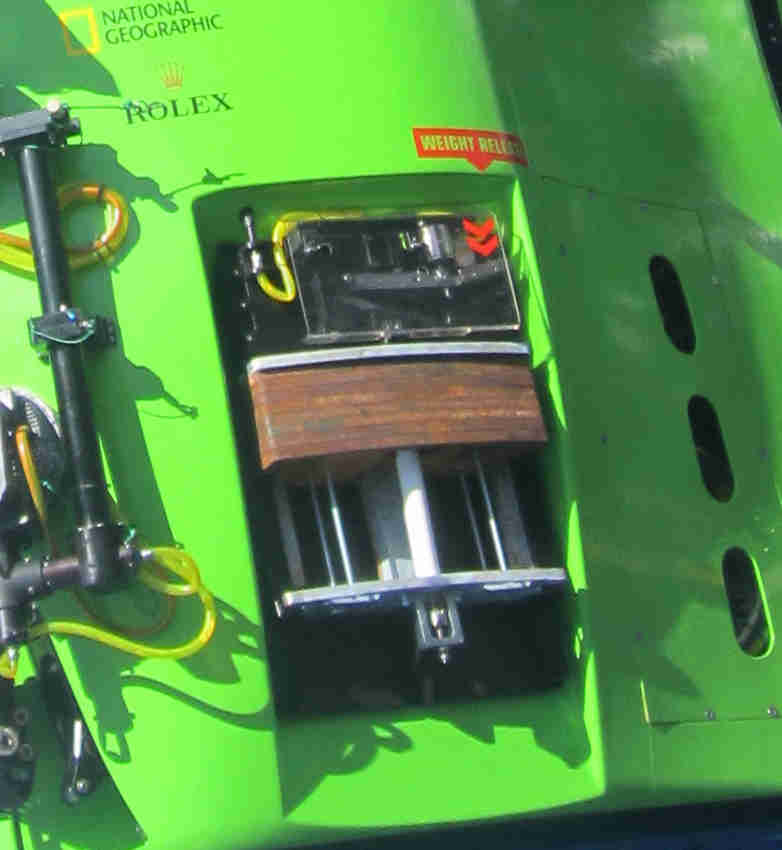
Figure 3. The ascent weights with multiple release means. Photo by Chris Symons. Used with Permission, Earthship LLC. |
|
|
|
Figure 4. DSC pressure hull with interior view of carbon fiber plastic inner shell. Photo by Ron Allum. Used with Permission, Earthship LLC. |
|
|
|
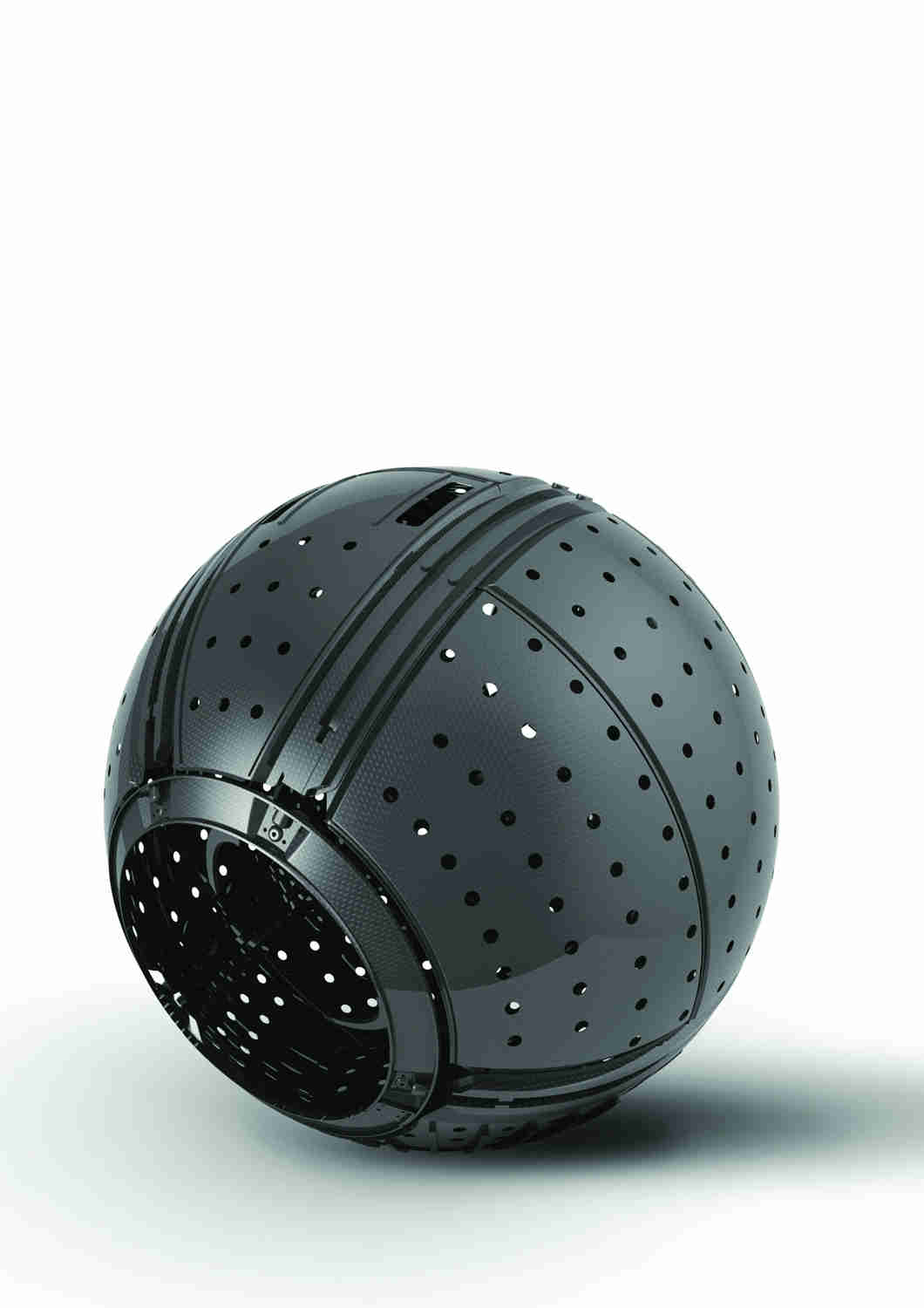
Figure 5. Multi-part, carbon reinforced plastic inner shell of the pilot sphere. Photo by Liam Mahoney, LSM Advanced Composites. Used with Permission, Earthship LLC. |
|
|
|
Figure 6. The DSC’s conic acrylic viewport. Photo by Bruce Sutphen. Used with Permission, Earthship LLC. |
|
|
|
Figure 7. The lower pod during construction. Photo by Bruce Sutphen. Used with Permission, Earthship LLC. |


 |
|
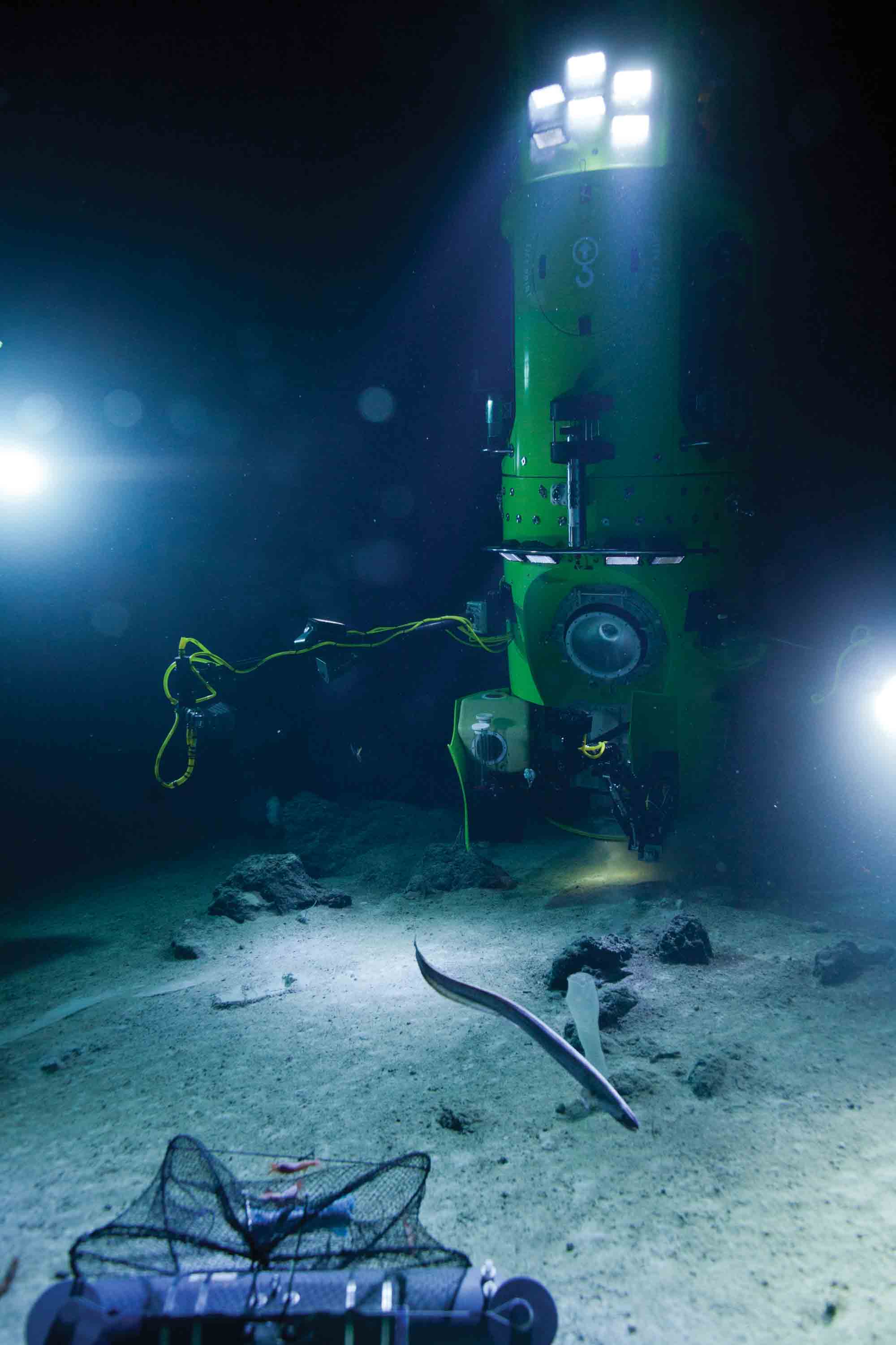
Figure 1. Co-designer Ron Allum pilots the DEEPSEA CHALLENGER across the rocky bottom at 850m near Falalop Island, Ulithi Atoll, Caroline Islands, FSM. Visible is the 2m camera boom, pan-tilt and stereo mini-cam, the manipulator, and conical viewport of the pilot sphere. The science bay door below the pilot sphere is seen open. Photo by Earthship LLC. |
It is a place where animals are accustomed to seeing bioluminescence not sunlight, an evolutionary result of 3.8 billion years of total darkness in that strange Other Earth far below the photic zone. Here is where ambient pressure could have the units, “tsi,” as in “tons per square inch.”
This is the final chapter in a three-part series that describes the new and legacy technology that defined the operational success of the DEEPSEA CHALLENGE Expedition.
Ballast and Trim
Unlike the Trieste, the DEEPSEA CHALLENGER does not require descent weights to get to the trench floor. The buoyancy of the DSC increased with depth because its net volume changed less with hydrostatic compression than seawater. Therefore, the vehicle is ballasted on the ship to be neutrally buoyant at the target depth of the given dive.
An adjustable-trim system using steel-shot held by an electromagnet is incorporated to allow the vehicle to maintain neutral buoyancy when taking on samples or exploring up a slope or a rising feature.
The ascent weight system provides the vehicle with a safe return to the surface (Figure 3). There are five levels of redundancy on three separate circuits. The primary method of dropping the weights is a pilot-operated switch that cut the power to the electromagnetic coils holding the lever arms supporting the weights. The circuit can also be opened by an acoustic command from the surface in the event the pilot is incapacitated. If there is a power failure or the vehicle runs out of battery power, the electromagnetic coils will likewise de-energize and drop the weights. The second circuit uses a Frangibolt, similar to those used on DSV Alvin to drop its manipulator in case of emergency.
The third circuit uses a “GTR,” or galvanic time release, a bimetallic fuse that corrodes at known rate (e.g., 18, 24, 36 hrs). Three are used in parallel to provide the proper strength at the preferred time interval. The rate of galvanic corrosion is based on the ratio and mass of the anodic and cathodic materials, plus salinity and temperature of the ambient seawater. A significant effort went into calibrating these fuses to avoid a premature release that would unintentionally abort the dive.
Pressure Hull
The 43-in. Diameter x 2.5-in. thick pressure hull is fabricated from high tensile steel EN26, invented in the 1940s for use in large Howitzer-type gun barrels. It is an alloy similar to that used on DSV Trieste’s pressure hull in its 1960 deep dive (Figure 4).
All the equipment populating the pilot sphere is mounted to a high-temperature cure phenolic resin “whiffle ball” made by LSM Advanced Composites (Figure 5). This approach mitigated the need for any hard point fastenings to the pressure hull, while still allowing a dense packing of the interior space. Additionally, this shell-with-in-a- shell provides thermal isolation for the pilot and collection of condensation away from electronic circuits.
Acrylic Viewport
The hatch, situated at the lower pole, incorporates a custom designed conic acrylic viewport with a refractive index similar to seawater (Figure 6). The interior curvature of the viewport corrects for the 30% magnification that occurs with the change in refractive index from water-to-air through a flat plate viewport. The viewport was used for either pilot viewing or high-definition video.
Lights and Cameras
A 7-ft tall bank of 21 high-efficiency PBOF LED floodlights, affectionately called “light bricks,” are mounted to the face of the sub above the pilot sphere. Each light brick produces 3,000 lumens of white light. Another five light bricks were placed at strategic points on the sub. Above the 21 light bricks are two “Ty” lights. These unique PBOF LED lamps each produce 42,000 lumens in a spot pattern. Together, these provide immense light in the clear water of the deep ocean, easily illuminating up to 100 ft ahead of the sub. The lights can be turned on and off in banks by the pilot to vary the intensity for up-close imaging or wide-angle distance shots.
A 3-D HD CPG video pair is attached with a pan-and-tilt to an external 6-ft boom with 200-degree slough providing additional spatial awareness to the pilot. On the opposite side of the vehicle, a similar, but shorter boom is outfitted with a third “Ty” light, the 42,000 lumen PBOF LED spotlight.
Inside the sphere, the pilot can attach a Red Epic, an IMAX-quality 5K digital camera, to the interior of the viewport. The pilot then views images on an interior video display. A small video camera pair inside the sub captures 3-D images of the pilot.
Life Support
The life support system inside the DEEPSEA CHALLENGER is a dual closed-circuit rebreather system designed and developed by Ambient Pressure Diving (APD) working with John Garvin, life support specialist for Acheron. The system consists of a primary rebreather that feeds the cabin and a secondary “Bail Out reBreather (BOB) that is “closed loop” and used only in an emergency. The primary system provides over 100 hrs of life support under normal operating conditions. The back-up system utilizes the most current closed circuit rebreather technology to provide the pilot with a fully redundant system in case of an emergency. A small hand-held atmospheric analyzer, the Geotech G100, monitors the cabin’s carbon dioxide level as a back-up to the APD system.
Lower Pod The lower pod is a substantial fiber-reinforced toughened epoxy structure that fits over and around the pilot sphere on the main vehicle (Figure 7). In addition to housing the hydraulics, compensators, robotics, science payloads, adjustable trim, and ascent weight systems, it also protects the pilot sphere by absorbing an impact with the seafloor by flowering the components away from the sphere and redirecting the remaining load into the structural syntactic beam. While robust, the lower pod
maintains the graceful lines of the sub’s hydrodynamic body.
Other design elements
There is a design mandate that every implodable volume on the manned vehicle be filled with Fluorinert, a 3M product used in transformers. The crystal-clear, high-dielectric fluid has a specific gravity of 1.9 that has to be considered in calculating buoyancy and trim. The housings in question include the external MetOcean strobes and RDF beacons and the Iridium phones, packaged in a 10-in. Diameter Nautilus-Marine Vitrovex glass spherical housing.
Subsurface Communications
The DSC uses an L3 Nautronix long-range acoustic modem to transmit and receive both voice and data communications. It can also calculate total distance (range) between modems. The L3 was initially envisioned to provide two-way data and communication between the triad of vehicles—the DEEPSEA CHALLENGER submersible, the M/V Mermaid Sapphire, and the twin unmanned Landers—and substantially achieved that goal.
The L3 Nautronix system uses matched acoustic modems that operate between 8 and 12 Khz and can transmit voice further than 15 km. This had been tested at horizontal distances, but never to depths of 11 km. Thermoclines, haloclines, varying densities, and surface noise all affect the performance of the system. As the project progressed to deeper depths, the methods of operating the system changed empirically to improve the odds of success.
The transmitted source level is attenuated significantly through 13 to 15 km of slant range; therefore, the L3 Nautronix was designed with a very sensitive receiver. In the field, this sensitivity makes background noise the largest problem, mainly that generated by ship’s propulsion and machinery and picked up by the topside transceiver hydrophone. Eventually, the entire topside transceiver system was placed in a RHIB (Rigid Hull Inflatable Boat) boat with its dunking transducer suspended on a long cable, increasing the distance from the mother ship’s noise to clearly resolve the attenuated signal from DEEPSEA CHALLENGER.
The control system of DEEPSEA CHALLENGER automatically uses the data modem feature to transmit measured depth, O2, and CO2 levels inside the hull, battery voltages, and other critical information. For this mode, a PC running a small application was connected to the L3 acoustic modem.
The submersible pilot and shipboard communication team can also communicate using text messages.
Pilot Training
Using the same male tool for fabricating the pressure hull, two additional pilot spheres were made using 5/8-in. Carbon steel. The first was used for the pilot sphere ergonomic and general arrangement/ equipment layout. It was then integrated into a refrigerated simulation chamber for conducting pilot and emergency training with all of the systems and components that are in the actual DSC vehicle’s pilot sphere. The second sphere was not used.
Emergency Procedures
Provision is made to jettison the entire ascent weight system, and the adjustable ballast system on the science door in the event of entanglement. In case of fire and noxious gases, the pilot has a separate closed-circuit emergency breathing system with a full face mask as described above. Provision is made for pilot egress at the surface with the submarine still in the water.
Future
The DEEPSEA CHALLENGER submersible was gifted to Woods Hole Oceanographic Institution where it will be conserved and studied to identify innovations that can be harvested and applied to future vehicles of all classes. For further information contact Anthony Tarantino at atarantino@whoi.edu.
More information on the submersible and landers may be found online at http://deepseachallenge.com and http://www.whoi.edu/main/deepseachallenger.
Watch for the movie DEEPSEA CHALLENGE 3D in theaters on August 8, 2014.