July - Technology of the DEEPSEA CHALLENGE Expedition (Part 2 of 3 DEEPSEA CHALLENGER)
Ocean News
By: Kevin Hardy, Global Ocean Design LLC; Bruce Sutphen, Sutphen Marine LLC; and James Cameron, Earthship Productions LLC
Introduction
Driven by a deep curiosity to explore hidden places, James Cameron's DEEPSEA CHALLENGE (DSC) Expedition could have claimed the motto "Vade, et vide," meaning "Go and see." But to go and see the rolling fields of the lands submerged 7 miles underwater was an unimaginably complex effort led by a single, passionate visionary. The challenges were huge and the danger real.
 |
|
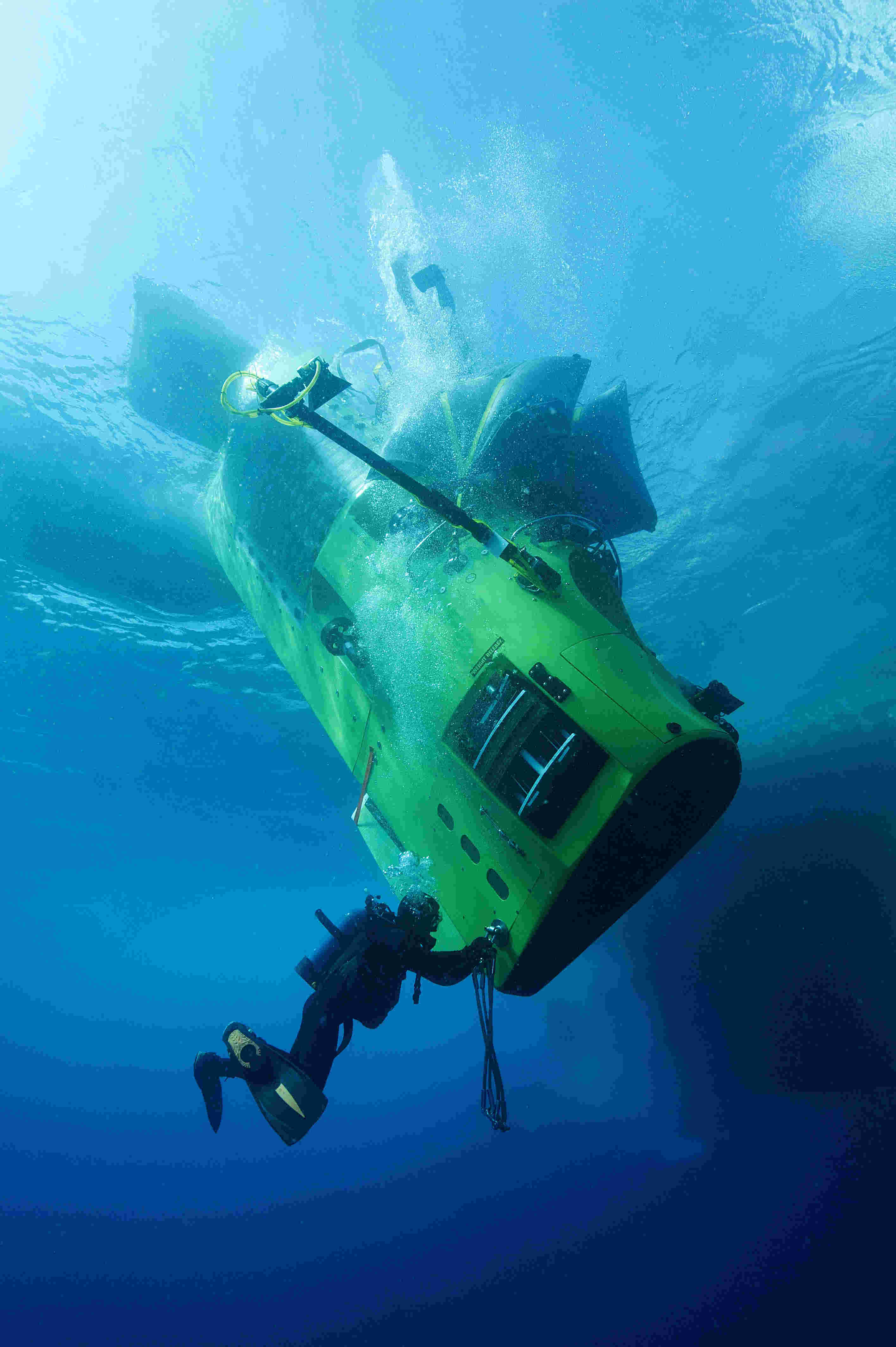
Figure 1. DEEPSEA CHALLENGER is prepared for launch by two divers during the DEEPSEA CHALLENGE Expedition. Photo by Charlie Arneson, used with permission, Earthship LLC. |
It had been over 50 years since the last humans visited the extreme hyperbaric world of the Mariana Trench. Only a lack of access, not interest, has kept us away. That changed forever on March 26, 2012. Explorer and Filmmaker James Cameron roamed freely for hours in the Challenger Deep, in a oneman submersible he codesigned with Australian engineer Ron Allum. Cameron vowed to leave the door open behind him as he left the trench floor. Twin unmanned landers, discussed last issue (ONT, June 2014), complemented the human exploration. This second of a threepart series will begin the discussion of the technologies, both new and legacy, used in the making of the manned submersible. Part 3 in next month's issue will complete the outline of the submersible technologies.
Science
A number of significant biological and geological findings were made through the expert observations and targeted sampling performed by the DSC vehicles. A number of peer-reviewed scientific publications by respected oceanographic and planetary science institutions, co-authored with James Cameron and other DSC team members, have been published or are in process.
Design and Project Objectives The DEEPSEA CHALLENGER manned submersible was developed for scientific research in the hadal depths. The development, construction and operation were privately funded on an aggressive timeline, requiring the major cost centers be identified upfront. Development speed and cost effectiveness were improved by capitalizing on interchangeable technologies shared across multiple undersea vehicle types (Figure 1).
The size of the submersible was quickly understood to drive both the cost of building the vehicle and its operations. The submersible size determined the size of the surface support ship needed, its availability and associated costs, including crew, fuel, food, deck gear, logistic support, and operational weather limitations. The Pilot Sphere would also require pressure testing, and that had limited choices above a certain size. With all factors weighed, Cameron made the final call that a single occupancy vehicle was the optimum solution.
The resulting as-launched vehicle air weight was ~12.0 metric tonnes (≈13.2 imperial tons), within an overall envelope measuring 8 x 6 x 27 ft.
 |
|
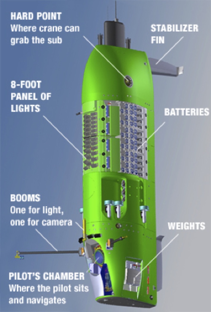
Figure 2. General outboard view of the DEEPSEA CHALLENGER, used with permission, Earthship LLC. |
 |
|
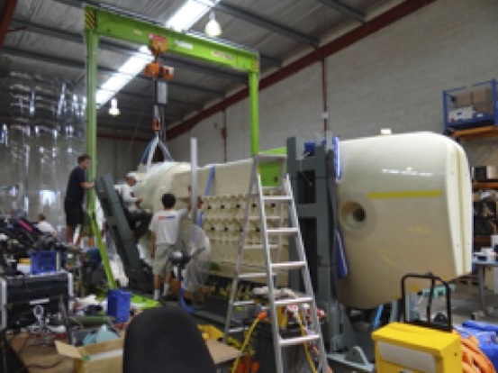
Figure 3. The DSC main spar before painting made of ISOFloat syntactic. Photo by Tim Bulman, used with permission, Earthship LLC. |
 |
|
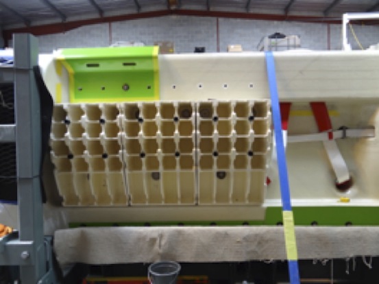
Figure 4. The PBOF LiPO slots made of ISOFloat syntactic. Photo by Ben Grant, used with permission, Earthship LLC. |
 |
|
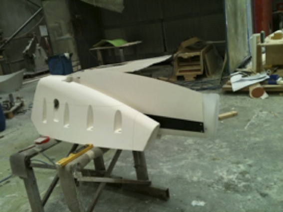
Figure 5. DSC stabilizer fin and tiplet sub-assembly. Photo by Bruce Sutphen, used with permission, Earthship LLC. |
Vehicle Operational Considerations
The vehicle design gave consideration to the full environmental characteristics of the deep dive, including the high delta ambient pressure, wide temperature range of operation, seawater/ galvanic corrosion, ambient light, convection-driven ocean currents, change in density, operational launch and retrieval sea state limits, bottom conditions, communications, data transfer, navigation, acoustic field, vehicle hydrodynamics/ride quality, and any potential biological fouling.
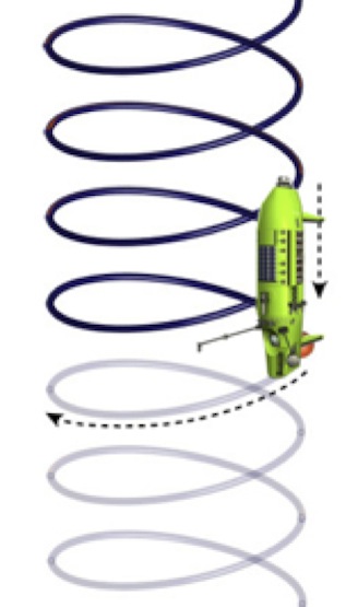 |
| Figure 6. Passively activated stabilizer fins induce a small yaw moment constraining the line of flight to a helical path. Image by Nico Danan, Planet OS/MarinExplore, used with permission, Earthship LLC. |
 |
|
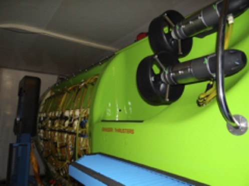
Figure 7. The DSC on deck with vertical thrusters and LiPO battery pods visible. Photo by Tim Bulman, used with permission, Earthship LLC.
|
In order to create a manned vehicle to dive the Challenger Deep, only 11° above the equator, the vehicle had to accommodate the thermal shock of moving from a hot deck under a blazing tropic sun to a cooler sea surface, then an extended cold soak at 33°F at 6.83 mi below the ocean surface.
Radio frequencies are filtered in the first inches of depth, making it easier to talk to a robot on Mars than a manned submersible in the sea. There are also significant currents in the water column that can dislocate a submersible from its glide path and scramble acoustic signals used to track the submersible's position and communicate with its pilot.
In the round-trip journey into the deepest ocean trench, the ambient pressure changes from 1 bar/14.7 psi at the surface to 1,100bar/16,300 psi at floor of the trench. The submersible crosses the almost 7-mi distance downward in about 120 minutes. It hurtles on the way back up, covering the same distance in only 70 minutes.
Buoyancy
The syntactic served the dual purpose of buoyancy and structural support (Figure 3). The personnel sphere, batteries (Figure 4), thrusters — everything — was hung directly off of the structural foam. No syntactic foam currently made for use at hadal depths met the structural and elastic requirements of the manned submersible design. A considerable effort was put into developing and producing a new composite material, later named ISOFloat, made of hollow glass micro-spheres and structural fiber secured in a toughened epoxy matrix. The foam has a specific gravity of 0.7 and experienced half the volume change as the seawater, increasing the vehicle's buoyancy with depth. The rest of the vehicle was fabricated from polyester fiber-reinforced, toughened epoxy laminates with the ISOFloat structural cores where merited.
Stability
The initial vehicle geometry had dynamic instability issues as it approached its terminal descent and ascent speeds; however, an integrated Computer Fluid Dynamics (CFD) study and scaled modeling program resolved the issues through tweaks in the volumetric distribution, boundary layer manipulation and passively activated stabilizer fins (Figure 5), which not only constrained the role instability but also induced a small yaw moment constraining the line of flight to a helical path (Figure 6).
The stabilizer fins (aka: Sut-Fins) were fabricated from ISOFloat structural syntactic foam with a 7000-series aluminum spar and UHMWPE (ultrahigh molecular weight polyethylene) tiplets. By using these materials, the fins had a defined near-neutral buoyant moment allowing them to actuate via fluid flow as the vehicle ascended or descended.
Fairings Submersible fairings were fabricated from a near-neutrally buoyant fiber-reinforced laminate utilizing a toughened epoxy matrix. A vacuuminfusion process lowered the probability of implosive voids. The polycarbonate mast housed the vehicle's surface c o m m u n i c a t i o n equipment (e.g., VHF, Iridium Phone and LED strobe lights).
Vehicle Performance and Design
It was felt that there was more to be learned from exploring the nooks and crannies of the ocean floor than in the mid-water, so the vehicle was designed to transit quickly through the 7-mi water depth. This was accomplished by the radical notion of limiting the cross-sectional frontal projected area and elongating the height. The sub had the appearance of a canoe on end (Figure 2). On deck, lying horizontal in its support cradle, it looked like a more traditional submarine. But underwater, it is a creature of the sea, diving vertically like a blue whale plumbing the depths or pirouetting on the seafloor like a graceful Siphonophorae
Power
The stored Lithium Ion battery power of the DSC could be configured to be as high as 96 KWh, though the storage used on the 12 manned dives was between 76 and 84 KWh. These came from a maximum of 96 PBOF LiPo battery packs, divided into three busses. The sub could operate off of a single buss in emergency mode. All power and control signals were passed through the pressure hull via four discrete penetrators in the penetrator plate at the upper pole of the pressure hull.
Controls
The main controls of the vehicle were shared between a joystick control and two graphic user interfaces (GUIs) incorporating two standard touch screen tablet displays.
Benthic Translation and Maneuverability
There were 12 PBOF thrusters on the vehicle: 6 vertical and 6 horizontal. These were used for maneuvering on the seafloor and up slopes, 3 kts horizontal and 3.5 kts vertical (Figure 7).
Next month
In Part 3, we will examine the DEEPSEA CHALLENGER's ballast and trim systems, pressure hull and acrylic viewport design, life support systems, lower pod design, subsurface communications, pilot training, and emergency procedures and conclude with a look into the DEEPSEA CHALLENGER's effect on future ultra-deep exploration.
Watch for the movie DEEPSEA CHALLENGE 3D in theaters August 8, 2014.