June Editorial - TECHNOLOGY OF THE DEEPSEA CHALLENGE EXPEDITION (Part 1 of 3: The Landers)
By: Kevin Hardy, Global Ocean Design LLC; Bruce Sutphen, Sutphen Marine LLC; and James Cameron, Earthship Productions LLC
 |
|
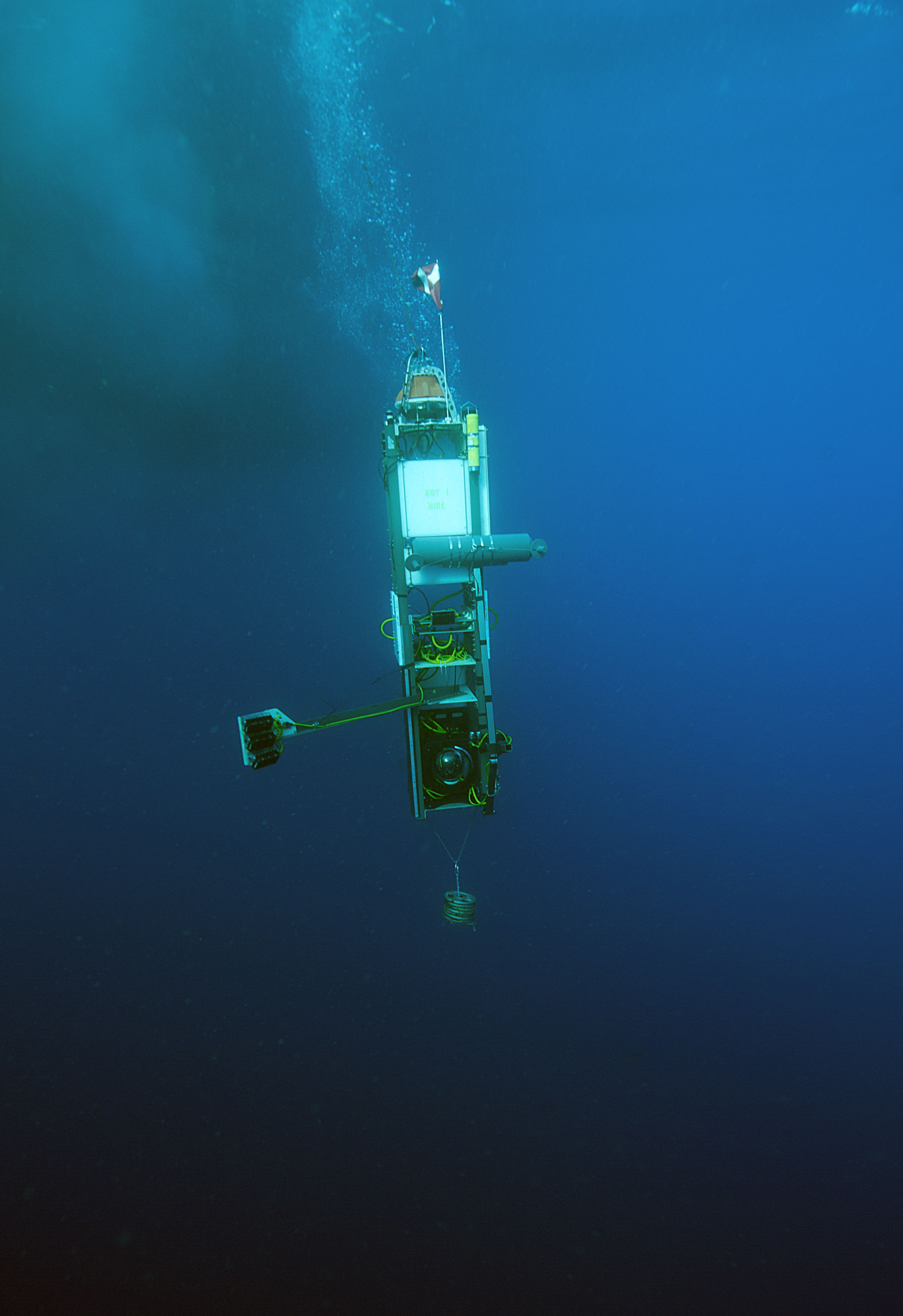
The DEEPSEA CHALLENGE lander, DOV MIKE, is photographed heading for the bottom of the New Britain Trench near Papua New Guinea. Photo by Charlie Arneson, used with permission, Earthship Productions. |
Introduction
Virtually all oceanography has been done in the upper 6 km of the ocean, and very little in the 5 km below that in the deep region known as the “hadal zone.” Created by the titanic planetary forces of plate tectonics, earthquakes, volcanoes, tsunamis, and countless unknown species are born there. A lack of access, not interest, has kept the hadal zone living in our common language as something “unfathomable.”
On March 26, 2012, a day like only one other in the entire history of man’s reach into the sea, Explorer and Filmmaker James Cameron resolutely piloted a one-man submersible to the bottom of the Challenger Deep in the Mariana Trench. Once there, he roamed freely for hours in the dark hallways of Neptune’s dungeon as no one had ever done before. To make that happen, the design limits of both manned submersible and unmanned landers were pushed to include the newest ideas and developments, with legacy technology forming a broad foundation.
In his quest to reignite scientific interest and inspire world awareness of the forgotten lands of the ocean trenches, Cameron’s DEEPSEA CHALLENGE (DSC) Expedition developed a radically new submersible and twin unmanned “landers” as his primary vehicles of exploration. This two-part series will highlight the technologies, both new and applied, used in the making of the manned and robotic machines that could operate in the extreme pressures of Earth’s ocean trenches.
Science
A number of significant biological and geological discoveries were made through the expert observations and targeted sampling performed by the DSC vehicles. Giant amphipods, larger and deeper than seen before, and the discovery of bacterial mats clinging to the downslope faces of jagged rocks at the very intersection of subducting plates, are but two examples. Many of the biological discoveries are recounted in the AGU Ocean Sciences 2014 paper “Submersible Exploration of the World’s Deepest Megafaunal Communities through the DEEPSEA CHALLENGE,” authored by Natalya Gallo, Center for Marine Biodiversity and Conservation, Scripps Institution of Oceanography/UCSD, and co-authored by key members of the expedition including James Cameron. Other peer-reviewed scientific publications are in process.
Shared Technology
The expedition demonstrated the practicality of interchangeable technologies shared across multiple undersea vehicle types: the submersible, the twin landers, and an ROV. Pressure compensated batteries, LED lights, stereo HD cameras, and acoustic navigation and communications systems found similar application on the different platforms.
Cameron’s DEEPSEA CHALLENGE Expedition brought together multiple undersea vehicles to gain the advantages of each, while balancing corresponding disadvantages. The submersible provided the suite of human senses, tactile ability, depth, and payload capacity, but was limited by pilot endurance. The ROV provided imaging, tactile ability, and some payload capacity, but was tethered to a ship and had a limited operating depth. The landers have no mobility or the ability to recognize their immediate environment in detail and selectively sample it, but have persistence and freedom from the ship.
Landers
The “landers” are unmanned free vehicles that transit in free fall from the sea surface to the seafloor, landing upright on the alien surface of that Other Earth. They remain in place, sampling, measuring, and imaging, until acoustically commanded to release their anchor weight and begin their reciprocal free fall upward, back to sunlight and atmosphere.
Advancements in superthick-wall borosilicate spherical housings from Nautilus Marine Service® provide a cost-effective option for ocean trench work, simultaneously providing both an instrument housing and buoyancy. The Vitrovex® spheres can be polished to make a camera viewport, drilled and spot-faced for connectors, are impervious to corrosion, are invisible to light and electromagnetic waves, and made of an abundant and inexpensive material. Their downsides include being prone to conchoidal fractures if struck a glancing blow, surface spalling, and the potential of immense implosive force by catastrophic failure. Some manufacturers of the past produced glass with inclusions of air and char, non-concentricity of inside and outside diameters resulting in variable wall thickness, surface striations, and improperly lapped sealing surfaces — intolerable imperfections in the ultra-deep sea.
The landers utilized a large volume of the same syntactic foam made for the submersible by Acheron® to reduce the potential of an implosion. This was roughly divided into 2/3 for fixed buoyancy and 1/3 for variable buoyancy.
Other component technologies required similar improvement, and piece-by-piece, engineers and their companies, inspired by the challenge, created the key components able to survive ambient pressures of 1,100 atmospheres.
Interchangeable payload modules were being built in parallel, requiring flexibility in the payload bay of the lander.
Basic Description
The lander vehicle body was approximately 14-ft tall, with a narrow width and depth, approximately 2.5 ft x 3 ft, with buoyancy high and weight low, yielding excellent self-righting performance (Figure 1). This also provided a small frontal projected area during descent and ascent, resulting in vertical transit stability, with minimal horizontal offset. The box structure made infield adaptations simple. Use of low specific gravity materials such as extruded fiberglass shapes, HDPE sheet, and 6061 aluminum plate minimized in-water weight, decreasing buoyancy requirements. Consideration was given to metacentric stability on descent, at the seafloor, on ascent, and at the surface.
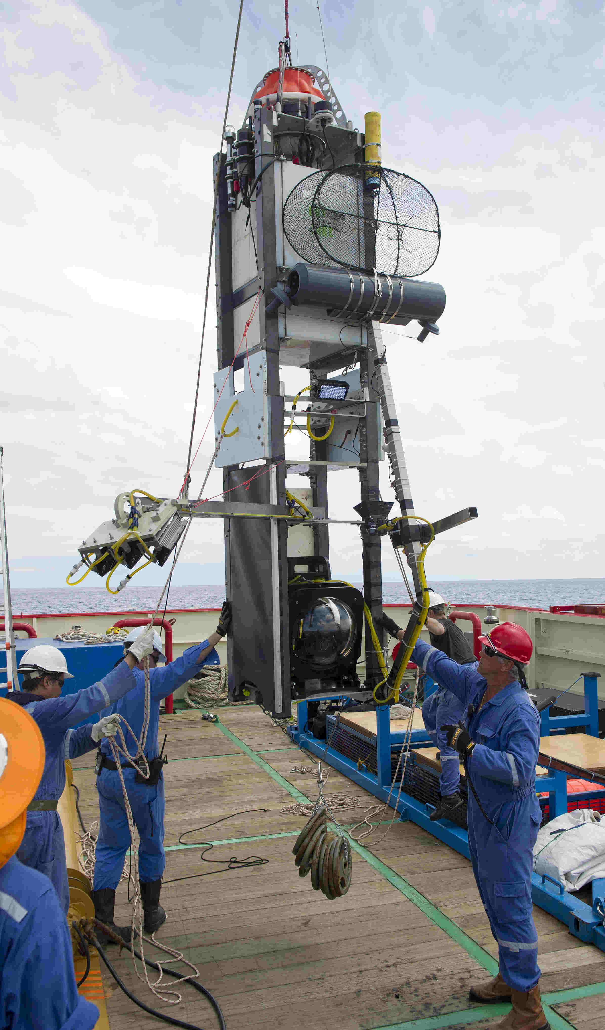 |
| Figure 1. The DEEPSEA CHALLENGE Alpha Lander, DOV MIKE, is lifted by crane during deployment. Photo by Charlie Arneson, used with permission, Earthship Productions. |
Frame The lander frame was built in two sections to allow disassembly for transport. HDPE doubler plates at the mid-section joint reinforced the FRP frame during deployment and recovery operations. The vehicle was laid horizontally on deck during transport, pre-launch preparation and post-recovery servicing. Because of the vehicle’s overall size and weight, use of a crane or A-frame was mandatory.
A 6061-T6 welded and heat-treated aluminum lifting bale was placed at the top. The SolidWorks® design was evaluated using FEA and validated by physical testing. Dual toggle releases were located at the bottom of the frame, providing redundancy.
Two 17–in. x 23-mm thick Vitrovex glass spheres were used, one for the Command/Control sphere at the top of the frame, the other for the Camera sphere, located at the bottom of the frame. Barbell weights were added below the camera sphere to cancel its buoyancy and keep the weight low.
Ballasting and release mechanism A clump weight was made of 85 lbs of cast iron barbell weights. A chain was run through the middle holes, then fastened back on itself, making a closed loop through the weights. The loose end of the chain is shackled to a large welded ring. Through this ring a second length of chain is passed. Each end of the second chain is held by a separate toggle release mechanism located on either side of the base of the lander. Both toggle releases are held closed by an Edgetech® Inconel burnwire element. One Edgetech burnwire is connected to the command/ control sphere, where it may be directed by acoustic command to corrode and release its chain end. The second Edgetech burnwire is connected to an independent, stand-alone countdown timer. Should the acoustic command release system fail for some reason, the back-up countdown timer will initiate the burn of the second burnwire after a pre-set time interval of up to 99 hours. On short duration drops, a Galvanic Time Release (GTR) was also added as a tertiary backup.
Glass housing design and manufacture The Vitrovex glass housings included drilled and spot-faced penetrator holes. Some refinement continued on the geometry of the edge chamfer to minimize spalling. Some exterior surface spalling was evident after the deepest dives as well. This may be due to residual stress created by localized cooling during the manufacturing process. The spheres were tested to 1,000 atm at Vitrovex plant in Germany. Later testing was done to 1,225 atm at Deep Sea Power & Light®
Provision was made for two bulkhead connectors and a single purge port. The purge port is used to cycle air over a desiccant to dry it prior to deployment, preventing condensation on electronics or camera lenses at the cold temperatures found at depth.
Command/control sphere The command/control sphere housed an Edgetech BART Board acoustic transceiver circuitry, recovery beacons, and batteries. The Edgetech BART Board was selected for acoustic command and control because it has two release commands, with an optional daughter board providing four more. These proved invaluable at-sea. The BART system was successfully tested in August 2011 in the Mariana Trench Sirena Deep at 10,800 m using a topside Edgetech Model 8011M Acoustic Tranceiver deck unit.
 |
|
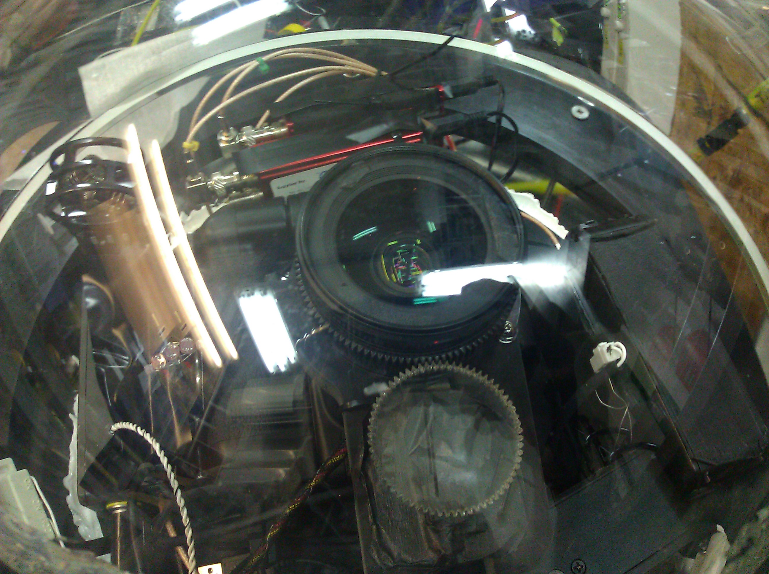
Figure 2. A Canon 5D camera is seen through the optically polished Nautilus Marine Vitrovex glass housing. Photo by Charlie Arneson, used with permission, Earthship Productions. |
The camera sphere housed a still/video camera, a programmable camera/light controller, and the recorders for the external stereo camera pair, described in detail below.
A 12.75-in. D x 1/8-in. aluminum plate is bolted to a PVC ring mount secured by 3M® 5200 marine adhesive to the interior of each hemisphere. The upper plate holds the recovery beacons and battery. The lower plate holds the Edgetech BART board and battery. Below the lower plate, the bulkhead connectors bring copper connections through from the outside.
The landers incorporated MetOcean/Novatech strobe lights (ST-400) and RDF (RF-700) beacons, minus pressure cases, inside the upper sphere. An RF-700AR, an RDF with remote antenna, was transferred to the submersible. An ST- 400 strobe with a custom acrylic head made by Acheron, and a standard RF-700 RDF were mounted to the frame outside the sphere.
Duracell® alkaline cells supplied battery power for the command/ control sphere and back-up timers. The camera internal to the sphere used rechargeable LiPO camera battery packs. The PBOF LED cinemagraphic lights and stereo cameras were powered by Acheron PBOF LiPO battery packs made for the DEEPSEA CHALLENGER submersible.
Camera sphere The camera, the controller, and all other recorders and components were mounted in one hemisphere. The matching hemisphere was polished to optical clarity and was closed once the detailed pre-cruise checkout was complete.
Imaging system
The DEEPSEA CHALLENGE Expedition required imaging systems far superior to any ever utilized at these depths. HD stereo cameras made by the Cameron Pace Group®, spaced ocular distance apart, recorded stunning images of life and land in the ocean trenches.
The spacious interior volume of the Vitrovex glass spheres and ability to take high quality images directly through their polished glass walls was a powerful combination. After exhaustive comparison tests, a Canon 5D Mark II DSLR was selected by Larry Herbst, a seasoned underwater imaging expert, for its high-resolution sensor and lowlight capabilities (Figure 2).
In the black depths of the sea, the camera would need to shoot with the lens nearly wide open — resulting in extremely limited depth-of-field. Accurate focusing was critical. A 1-ft deep 50-ft long focusing trough was built to gather focusing data through a horizontal water column, with the camera lens positioned close to the inner apex of a polished glass hemisphere.
For lighting, the lander was outfitted with four PBOF LED “light bricks” made for the DEEPSEA CHALLENGER submersible.
Connectors and cabling
MacArtney SubConn® PBOF connectors were used with the LED lights, pressure compensated LiPO batteries, and the L3 comm controller. Standard SubConn connectors were used with adapter ports to bridge between standard thread lengths and the longer threads needs for glass spheres. A special high-pressure fitting was also made by the Lander Team to adapt a fiberoptic feedthrough, designed by Acheron, to the lander camera sphere. Connectors made by SeaCon were used in the back-up timer and junction bottle.
L3 communication system The L3 Nautronix® unit is a long-range acoustic modem that transmits and receives both voice and data communications and can calculate the range between the ship and submerged platform. The unit was adapted with some effort to both the submersible and landers.
Given the attenuation of the transmitted source level through the 13 to 15 km operational slant range, the L3 Nautronix was designed with a very sensitive receiver. In the field, this sensitivity made background noise the largest problem, mainly that generated by ship’s propulsion and machinery picked up by the topside transceiver module.
Samplers and sensors Samplers on the lander included Niskin Bottle water samplers, fish net traps, and sediment corers. The fish traps worked well for amphipods. An additional Niskin bottle was mounted on the drop arm to lay on the seafloor and capture animals. The sediment samplers could benefit from further refinement.
The lander also carried an RBR® Ltd. DR-1050, a selfcontained, submersible depth recorder. The data provided insight to the landers’ fall rate, bottom time, release time, rise rate, and helped correlate the high definition stereo images of the life forms and geologic features with the extreme depths where they were found.
Testing
A saltwater basin at Scripps’ main campus was used to check air and water weights of unassembled components. Underwater connectors and fully assembled glass spheres were individually tested to 18,000 psi. Load tests were performed on critical load-bearing components. The first assembled lander was tested in San Diego Bay, then offshore San Diego at a 1-mi depth.
 |
|
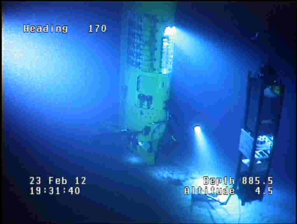
Figure 3. In a real-life-as-sci-fi image taken from an ROV, the DEEPSEA CHALLENGER submersible piloted by Explorer and Filmmaker James Cameron, rendezvous with the lander, DOV MIKE, at 885 m in the New Britain Trench near Papua New Guinea. Photo used with permission, Earthship Productions. |
Operation
The lander lay horizontally on deck to make access to all segments convenient and the platform more stable on deck in transit. With multiple dives, the deck crew became quite adept at handling the large lander
The lander dove largely straight down and back as expected. The fall and rise rates were high enough that little time was spent in any current, minimizing lateral offset. The Edgetech comm system provided good slant ranges. It was important to recover the biological samples as soon as possible.
Figure 3. In a real-life-as-sci-fi image taken from an ROV, the DEEPSEA CHALLENGER submersible piloted by Explorer and Filmmaker James Cameron, rendezvous with the lander, DOV MIKE, at 885 m in the New Britain Trench near Papua New Guinea. Photo used with permission, Earthship Productions.
Conclusion
The DEEPSEA CHALLENGE landers demonstrated their capability as robust and reliable payload haulers, test platforms, autonomous robotic camera, sampler, and sensor platforms. Utilization of common components across several vehicle platforms dramatically shortened the development time.
The remaining unmanned lander, along with spares and related surface support gear, was gifted to the Scripps Institution of Oceanography/UCSD. Combined with funding from HSRH Prince Albert II of Monaco, the hardware became the catalyst for the Scripps “Lander Lab,” a common resource for campus researchers and graduate students to access the deepest ocean depths.
Outreach
A hands-on project “Voyager Activity: Build Your Own Deep-Sea Lander,” was created for elementary school students by James Cameron and Kevin Hardy with Scripps Institution. You can download the design at https://scripps.ucsd.edu/news/voy ager-activity-build-your-own- deep-sea-lander.